a. Tính năng:
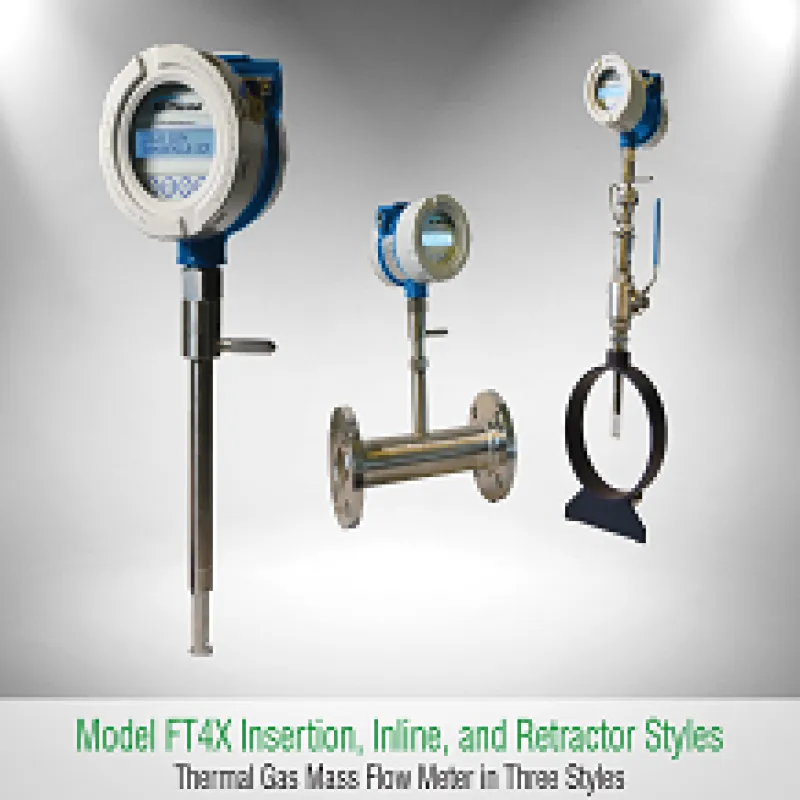
Các tính năng phổ biến cho Đồng hồ đo lưu lượng FT4X của Fox Heat Model:
Các biện pháp xử lý tốc độ dòng khí / tổng và nhiệt độ
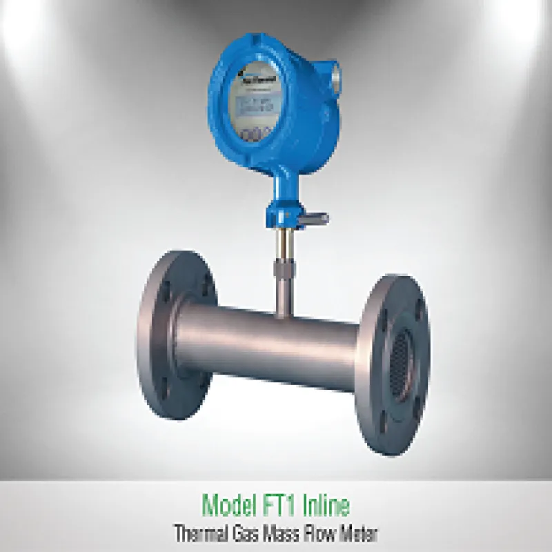
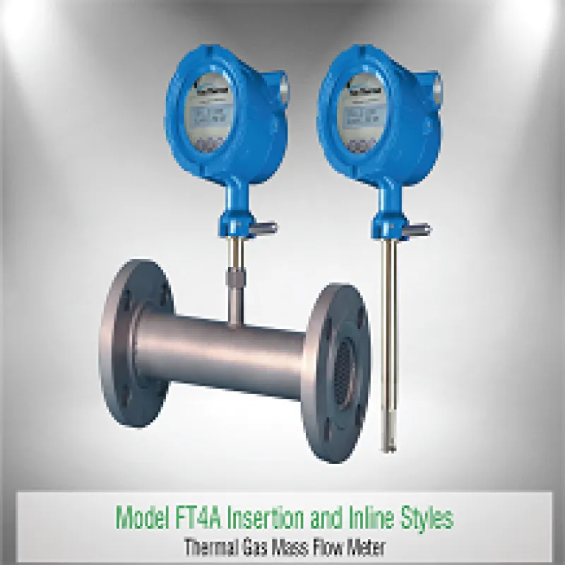
Đầu dò chèn (đối với ống 1,5 "- 70"); Các dòng chảy nội tuyến có đầu NPT (ống 1,5 "- 3"); Inline 150 # & 300 # Thân dòng chảy mặt bích (ống 1,5 "- 6")
Được trang bị DDC-Sensor ™ thế hệ 2 (Điều khiển kỹ thuật số trực tiếp)
Menu chọn khí mở rộng Gas-SelectX®. Chọn từ danh sách hỗn hợp khí / khí có sẵn để đo lưu lượng. Hiệu chuẩn theo dõi NIST
Trình ghi dữ liệu nâng cao với Đồng hồ thời gian thực và 40 tổng số hàng ngày 24 giờ
Thời gian hợp đồng có thể xác định ngày hợp đồng
Kết nối USB là chuẩn (Phần mềm FT4X View ™ miễn phí); Các giao thức truyền thông tùy chọn HART và Modbus RTU (RS485)
Bảng hiển thị và bảng cấu hình tiêu chuẩn
Hai đầu ra 4-20mA cách ly tiêu chuẩn: Kênh 1 được định cấu hình để biểu thị luồng, chỉ báo lỗi trên NAMUR NE43. Tùy chọn liên lạc HART; Kênh 2 được định cấu hình để chỉ ra dòng chảy hoặc nhiệt độ
Một đầu ra collector mở bị cô lập cho xung / báo động
Một đầu vào chuyển đổi để thiết lập lại tổng số
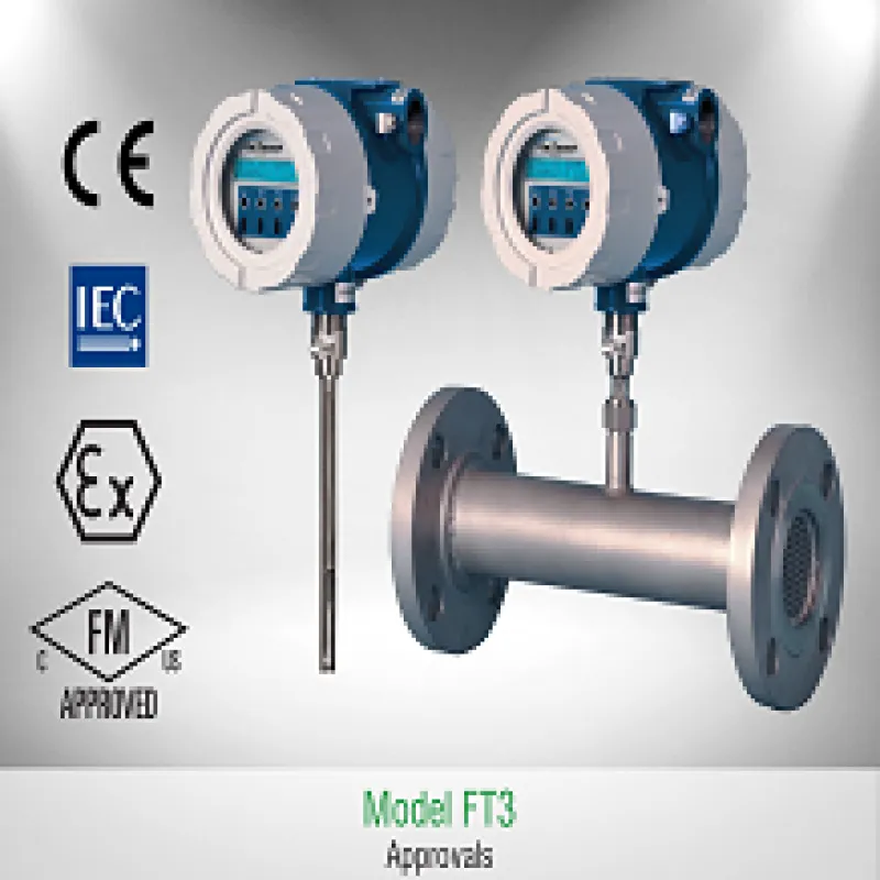
Nhấp vào tab Phê duyệt cho Chi tiết phê duyệt của Cơ quan FT4X
Xác nhận hiệu chuẩn với thử nghiệm CAL-V ™
Hiệu chuẩn theo dõi NIST
Phạm vi đo rộng
Độ chính xác của dòng chảy đối với không khí: ± 1% R ± 0,2% FS; Độ chính xác của dòng chảy đối với các loại khí khác: ± 1,5% R ± 0,5% FS
24 VDC trong vỏ bọc cục bộ hoặc từ xa
Máy đo lưu lượng khí Gas FT4X
b. Thông số kỹ thuật
Máy đo lưu lượng khí Gas FT4X
Fox Thermal Model FT4X Thermal Mass Flow Meter & Temperature Transmitter
Flow Accuracy:
Air: ± 1% of reading ± 0.2% of full scale.
Other Gases: ± 1.5% of reading ± 0.5% of full scale.
Accuracy specification applies to customer's selected flow range
Straight, unobstructed pipe requirement:
15 diameters upstream; 10 downstream.
8 diameters upstream; 4 downstream.
Flow Repeatability:
± 0.2% of full scale
Flow Response Time:
0.8 seconds (one time constant)
Temperature Accuracy:
± 1° F (± 0.6° C)
Calibration:
Factory Calibration to NIST-traceable standards
CAL-V™: In situ, operator-initiated calibration validation
Flow Units (field selectable):
SCFM, SCFH, NMPS, NM3/M, NM3/H, NM3/D, NLPS, NLPM, NLPH, MCFD, MSCFD, SCFD, MMSCFD, MMSCFM, SM3/M, SM3/D, SM3/H, LB/S, LB/M, LB/H, LB/D, KG/S, KG/M, KG/H, SLPM, SFPM, MT/H
Flow Rates:
Maximum range: 15 to 60,000 SFPM (0.07 to 280 NMPS)
Minimum range: 15 to 1,000 SFPM (0.07 to 4.7 NMPS)
Turndown:
up to 1000:1; 100:1 typical
Flow Ranges:
| Pipe Size |
SCFM |
MSCFD |
NM³/HR |
| 1.5" (40mm) |
0 - 840 |
0 - 1,220 |
0 - 1,325 |
| 2" (50mm) |
0 - 1,400 |
0 - 2,020 |
0 - 2,210 |
| 2.5" (63mm) |
0 - 2,000 |
0 - 2,880 |
0 - 3,150 |
| 3" (80mm) |
0 - 3,100 |
0 - 4,440 |
0 - 4,890 |
| 4" (100mm) |
0 - 5,300 |
0 - 7,650 |
0 - 8,360 |
| 6" (150mm) |
0 - 12,000 |
0 - 17,340 |
0 - 18,930 |
| 8" (200mm) |
0 - 20,840 |
0 - 30,020 |
0 - 32,870 |
| 10" (250mm) |
0 - 32,800 |
0 - 47,250 |
0 - 51,740 |
| 12" (300mm) |
0 - 46,600 |
0 - 67,180 |
0 - 73,500 |
| Pipe Diameter |
SCFM |
MSCFD |
NM³/HR |
| 0.75" (20mm) |
0 - 220 |
0 - 320 |
0 - 350 |
| 1" (25mm) |
0 - 360 |
0 - 520 |
0 - 570 |
| 1.25" (32mm) |
0 - 625 |
0 - 900 |
0 - 990 |
| 1.5" (40mm) |
0 - 840 |
0 - 1,220 |
0 - 1,325 |
| 2" (50mm) |
0 - 1,400 |
0 - 2,020 |
0 - 2,210 |
| 2.5" (63mm) |
0 - 2,000 |
0 - 2,880 |
0 - 3,150 |
| 3" (80mm) |
0 - 3,100 |
0 - 4,440 |
0 - 4,890 |
| 4" (100mm) |
0 - 5,300 |
0 - 7,650 |
0 - 8,360 |
| 6" (150mm) |
0 - 12,000 |
0 - 17,340 |
0 - 18,930 |
Note: To determine if the FT4X will operate accurately in other pipe sizes, divide maximum flow rate by the pipe area. The application is acceptable if the resulting velocity is within the velocity range above.
Note: Consult factory for flow ranges above those listed. Inline meters above 5,000 SCFM (7,900 NM3/H) air may require third party calibration.
Gas Pressure (max):
w/o Retractor: 740 psig (51.02 barg)
with Retractor: 150 psig (10.3 barg)
316 SS inline w/NPT ends: 300 psig (20 barg)
316 SS inline w/150lb flanges: 230 psig (16 barg)
CS inline w/NPT ends: 300 psig (20 barg)
CS inline w/150lb flanges: 285 psig (20 barg)
Check with factory for higher pressure options.
NOTE: When teflon ferrule option ordered, gas pressure is 60psig (4.1 barg) maximum.
Relative Humidity:
90% RH maximum; non-condensing
NOTE: Condensing liquids contacting the sensor can cause erratic flow indication.
Temperature:
DDC-Sensor™: -40 to 250°F (-40 to 121°C)
Enclosure: -40 to 158°F (-40 to 70°C)
Remote Sensor Enclosure: -40 to 158°F (-40 to 70°C)
Note: Display dims below -4°F (-20°C); function returns once temperature rises again.
Input Power:
Input power: 12 to 28 VDC, 6 watts max. (CE requirement)
Full input power input range: 10 to 30 VDC.
Inputs/Outputs
4-20mA Channel 1:
- Standard isolated 4-20mA output configured to indicate for flow; fault indication per NAMUR NE43. HART communication option.
- The 4-20mA load resistance must be 125 ohms or less when operating on 12 volt power and 600 ohms or less on 24 volt power.
4-20mA Channel 2:
- Standard isolated 4-20mA output configured to indicate either flow or temperature.
Pulse/Alarm:
- Isolated open collector output rated for 5 to 24VDC, 10mA maximum load, 0 to 100Hz (the pulse output can be configured to either transmit a 0 to 100Hz signal proportional to flow rate or an on/off alarm).
Remote Switch Input:
- Can be configured to reset the flow totalizer and elapsed time.
Port:
Micro USB communication port is standard.
Software:
The free PC-based software tool - FT4X View™ - provides complete configuration, remote process monitoring, and data logging functions.
Optional serial communication:
HART or Modbus RTU (RS485).
4-20mA and Pulse Verification:
Simulation mode used to align 4-20mA output and pulse output (if ordered) with the input to customer’s PLC/DCS.
Sensor Material:
316 stainless steel standard.
Enclosure:
NEMA 4X (IP67), aluminum, dual conduit entries with ¾" FNPT conduit entries.
Cabling to remote enclosure: 8-conductor, 18 AWG, twisted, shielded, 100 feet maximum.
Retractor Assemblies:
150 psig (10.3 barg) max.
N/A
Installation:
Fox Thermal-supplied compression fitting connects to customer-supplied 1" female coupling welded to pipe.
Compression fitting included with flow body.
c. Tiêu chuẩn:
CE: Approved
- EMC Directive; 2014/30/EU
- Electrical Equipment for Measurement, Control and Lab Use: EN61326-1:2013
- Pressure Equipment Directive: 97/23/EC
- Weld Testing: EN ISO 15614-1 and EN ISO 9606-1, ASME B31.3
FM (FM17US0061X) and FMc (FM17CA0032X): Approved
- Class I, Division 1, Groups B, C, D;
- Class II, Division 1, Groups E, F, G;
- Class III, Division 1; T6 or T4, Ta = -40°C to 70°C;
- Class I, Zone 1, AEx/Ex db IIB+H2 T6 or T4; Gb Ta = -20°C to 70°C; Type 4X, IP67
ATEX (FM17ATEX0015X): Approved
- II 2 G Ex db IIB+H2 T6 or T4; Gb Ta = -20°C to 70°C; IP67
- II 2 D Ex tb IIIC T85°C or T135°C; Db Ta = -20°C to 70°C; IP67
IECEx (IECEx FMG 17.0008X): Approved
- Ex db IIB+H2 T6 or T4; Gb Ta = -20°C to 70°C; IP67
- Ex tb IIIC T85°C or T135°C; Db Ta = -20°C to 70°C; IP67
ATEX and IECEx Standards: